Showing posts with label testing. Show all posts

Monday, April 5, 2021

Update: Wheelchair Computer Desk Feedback

 Back in February, we posted a blog describing the completion and delivery of our wheelchair computer desk to PathPoint. After a few weeks, we were finally able to get Mr. Meadth and Mr. Gil Addison together with his team to go over the design and get that long-awaited feedback.

Feedback from the end user is critical to the entire design process. For this particular project, the Academy had all sorts of unanswered questions: will the design function as requested? Does the screen angle suit a typical wheelchair user? How convenient is the keyboard position? Is the mechanical motion safe enough for general usage? Would a typical PathPoint resident be able to operate the remote control? What improvements could be made? While we don't currently plan on producing a Mk II, one project often leads into another and we improve our products by understanding their strengths and weaknesses.

Gil Addison (far right) together with his grateful staff

Mr. Meadth (center) joins in for the camera

Gil met Mr. Meadth together with six of the PathPoint staff members and together they went over the particulars of the design. You can watch the entire footage here, and a summary of design points is also included below.


As we draw this project to a close, thank you to PathPoint for being willing to work with us in an ongoing fashion! May our students always be inspired to use their God-given gifts with training and understanding, and we hope that the PathPoint residents are blessed through this simple gift.


Monday, July 27, 2020

Designed, Built, Flown!

You can't choose the hand you're dealt, but you can play it to win every time.

Along with every one else around the globe, the Providence Engineering Academy was dealt a tough hand in March. Having worked so hard in the lead-up to the major capstone project—to design, build, and fly a powered tethered aircraft—being asked to complete the project from home was not the situation that anyone wanted. But in the spirit of problem-solving, our junior and senior engineers faced up to the challenge. After all, what is engineering all about if not solving problems?

Our last post on this project ended with the four teams designing various aircraft components using professional-grade CAD software. They had sent their designs to Mr. Meadth, who began to 3D print their fuselages and tails, cut their carbon fiber, and CNC mill their wooden wing ribs, all from the comfort (?) of his garage.

The garage workshop: where the magic happens!

Over the course of several weeks, each team's delivery bag in the garage began to pile higher and higher with these manufactured components, along with advanced electric motors, lightweight lithium batteries, tissue paper, and other bits and pieces. Every last one of these components had been accounted for in duplicate: in a virtual CAD model and a complex spreadsheet. The CAD model held the actual design for manufacture, visualization, assembly guarantee, and mass/center-of-gravity prediction. The spreadsheet calculated wing and tail lift, which in turn yielded a force and moment balance, and also a redundant center-of-gravity prediction. (Redundancy is not a negative word in aircraft engineering!)

Quick science lesson: the center of gravity (c.g.) is where the sum of all weight is located. In other words, it's the point at which you could balance the aircraft on your finger, or where you could hang it from a string. It is determined by the masses and locations of the individual components, and it was critical that our uncontrolled aircraft had the center of gravity forward of the wing's lift force. Without going into the deeper explanation, having the center of gravity as close to the nose as possible means that the aircraft will be self-correcting and stable as it flies. Try attaching a paperclip to the nose of your next paper aircraft and note the dramatic improvement! This is why we ran two separate c.g. calculations using two different method—we wanted to absolutely confirm before manufacture.

Fresh off the printer, ready for delivery!

Sam and Josh work on RUBYGEM, papering and
doping the wings

Mr. Meadth delivered each team's bag directly to their respective homes. Upon arrival, each team worked hard to assemble the aircraft. This involved inserting carbon fiber spars into 3D printed wing boxes, stringing the wooden ribs evenly along the spars, covering the ribs with tissue paper, and then applying dope (a kind of water-based glue) to the paper. The doped paper dries and hardens into a kind of thin shell. The various electronics components were also connected and secured, along with the tail and undercarriage (landing gear).

At the same time, the simple tethering system had to be designed and implemented. The wooden stand sits in the middle of the flight path, and a 3D printed bearing served as an anchor point for the tether line. The tether was then attached to the wingtip. Some of the aircraft needed a little more rigging to ensure that the centripetal force didn't rip the wingtip loose!

Fast forward to the big day. Mr. Meadth made a final decision to hold the test flights in the gym, instead of outside. The smooth floor would take one more variable out of the equation, and the enclosed space would keep out any stray gusts. When your plane only weighs about 2 pounds and floats on the breeze, a gentle wind can be your worst enemy!

Thanos steps on to the court!

First up to the plate was Nolan and Pedro. Their purple and grey monoplane had a planned weight of 800 grams (less than a liter of water). The wingspan was a fairly standard 1.06 meters (a bit more than 3 ft), with a conventional tail style and taildragger undercarriage. Mr. Meadth tied their aircraft to the tether as the excitement mounted, and Pedro took the first turn at the controls. A gentle increase on the electronic throttle, and the affectionately named Thanos rose up beautifully into the air! Nolan took a turn as well, and the team scored two successful take-offs and two successful landings—the ideal outcome!

Plan view of Thanos, taken from the CAD model


Next up was Madison and Alena. Their Airplane Baby was ready to take its first steps, with Alena at the helm. In various shades of baby blue, the 540 gram winged wonder stretched out at an impressive 1.2 meter span (about 4 ft). Their wing aspect ratio (the ratio of wingspan to chord length) was a very healthy 12, almost double that of some other teams. But would it fly?

Airplane Baby gets ready to roll!

The girls produced a set of plans for their
written report

Without a doubt! Both Madison and Alena toured the gym in a somewhat rollercoaster fashion, the tether line being stretched to its limit. We estimated just a couple of feet clearance between the aircraft and the walls—enough to make any pilot sweat a little! But after a safe landing, all was well.


And now a little math. Replaying the video, it looks like Airplane Baby took about 3.5 seconds to complete a lap. If the diameter of the circle was about equal to that of the basketball court (50 ft), then the radius of the circle was half that: 25 ft. The speed of the aircraft through the air is equal to distance over time; the circumference of the circle divided by the time to get around that circle.

Circumference = 2π × radius = 157 ft
Speed = distance/time = 157/3.5 = 45 ft/s

This was about 36% faster than their design speed of 33 ft/s, which only goes to show that their stable aircraft design works just as well under a variety of situations. (It may also mean that their wings weren't as effective at generating lift as theorized!)

Sam and Joshua took to the floor after that, with a slender red aircraft tied to the tether: RUBYGEM. With a planned mass of 440 grams (almost exactly one pound), this was the lightest plane on display. Their rectangular wing planform spanned 1.08 meters, and they planned to fly at only 8 meters per second (26 ft/s). A lighter aircraft does not need as much lift to stay in the air, and so for any given wing design, it can fly slower and still generate the force it needs.

RUBYGEM steps out in style


As RUBYGEM gracefully lifted into the air, it was obvious that she indeed favored a slower style of things. Completing each lap in almost 5 seconds, the flight speed can be calculated at 33 ft/s. This is also faster than their design speed, which reinforces the theory that perhaps there is more inefficiency in the design than our theory accounts for. Sounds like real life, all right!

After successful landings, Mr. Meadth made the decision to head outside with the fourth aircraft: Big Wing Boy. And boy, was it big! At over 2 meters (6.5 ft) span, this multi-colored monoplane was just too big to spread its wings indoors. It was also designed to fly a little slower, and was very light for its size: 800 grams.

Big Wing Boy, taken from the design report

There was, however, one significant issue: while the design looked good in the CAD model and spreadsheet, the greater spans and sizes meant the physical attachment of the parts was just that much more difficult. The sheer size tended to stress the wing root joints more, so extra tension lines were strung between wingtips to help hold everything together.

Being outdoors on the grassy field, the decision was also made to give the aircraft a running hand-held start, because the wheels get caught in the grass. Risky? Yes! Mr. Meadth held Big Wing Boy aloft and kicked off his shoes to get the best launch speed possible. Given that an Olympic runner travels at around the 10 m/s mark, finding the necessary design speed of 8 m/s would be a challenge!


Ben cranked the throttle to a healthy roar, and Mr. Meadth began to dash around the circle. With a final push into the air, B.W.B. lifted up into the great blue yonder where he belonged. All seemed well... and then the unthinkable! Video footage analysis confirms that the carbon fiber stick connecting the wings to the tail tore loose from the aerodynamic loads, and no plane can ever do well without that stabilizing influence. This principle was, in fact, one of the central pillars of the second semester!

The moment of horror as the tail comes loose!

The aircraft wanted to perform, but just couldn't remain aloft. It plowed into the grassy field after only a few seconds of genuine flight. A quick repair and a repeat attempt was launched shortly thereafter, but another half-lap was achieved with similar results—with more permanent destruction this time! There was no third flight.

At the end of the day, what did we learn?
  1. Challenges are there to be overcome. The project could have modified to be easier, simpler, more virtual, you name it. But that kind of logic doesn't get you into the history books, and doesn't give the same kind of satisfaction. Greater levels of determination can turn challenges into victory.
  2. Theory is useful, but doesn't account for everything. Math and physics equations and computer simulations are incredibly useful, and with high-level manufacturing can be a very good analogy of the intended outcome. But the fact is that our theoretical calculations didn't account for a great many factors. This makes it all the more important to create robust, stable designs. The aircraft didn't perform exactly as intended, but they did perform in the real world.
  3. Aircraft need firmly attached tails. You may want to check the welds next time you hop on board your next 737.
Congratulations to our eight aircraft engineers, and many blessings on the four seniors, now alumni: Ben, Todd, Alena, and Madison. You have completed something to be proud of!

Monday, May 11, 2020

Design, Build, Fly!

Our students can't be together in person right now, but nothing is going to stop them finishing the capstone design/build/fly project for the 2019-2020 year. With digital tools in their hands and computer-controlled manufacturing equipment at the other end, our budding engineers, now sheltered in place, are experiencing the reality of a modern workflow. Even before the advent of COVID-19, many companies routinely collaborated from around the globe, producing advanced designs using international teams. Although not our first choice of preference, we're taking the challenge head-on!

Mr. Meadth teaching aircraft stability via Zoom

The first step for our skillful students was to learn the ins and outs of classic aerodynamics. In January, February, and March, the eight juniors and seniors studied airfoil behavior, lift and drag equations, and learned how to use weighted averages to find the center of gravity of a complex system. Our team learned the different parameters of airfoil design, and used virtual wind tunnel tests to predict just how those airfoils would respond in real life.

The virtual wind tunnel program XFoil: a classic
historical aerospace simulation! Note the cambered
airfoil shape at the bottom, with the yellow boundary
layer on top and the blue one below

Even more important was the notion of stability. What makes some physical systems stable, and others unstable? The incredible hexacopter drone that emerged in the first semester was inherently unstable, which means that it will rapidly flip and roll and fall out of the sky if the onboard computer-controlled gyroscopes were to stop doing their job. The gyroscopes sample the position and orientation of the drone dozens of times per second, and send minor corrections to the six motors, all without the pilot on the ground ever knowing it. Stable drone flight is an astounding human accomplishment, powered by calculus and implemented by technology, but it is not inherently physically stable.

On the other hand, the powered fixed-wing aircraft in this project must be physically stable. Tethered to a central post and flying continual circles, the aircraft will have only one remote-control channel controlling the power to the motor. There are no ailerons, elevators, rudder, or flaps. Without moveable control surfaces, the aircraft must be designed to constantly self-correct all by itself. If the nose dips down a little because of a gust of wind, it must automatically seek to find level again. If it rolls a little too much to one side, it needs to roll back again. The principles involved hold true for most common vehicles: cars, bicycles, even the caster wheels on supermarket carts.

Having mastered the physics involved, the students set about the difficult task of starting their design. No kits, no instructions, no fixed starting point! In teams of two, the students created a complicated spreadsheet filled with graphs and tables and physics equations, listing masses and locations and forces and moments. The students also designed a multi-part CAD model according to those numbers using the professional-grade online platform Onshape; ideally, the CAD model, the spreadsheet design, and the manufactured plane itself will end up as three matching representations of the same reality.

Pedro's and Nolan's aircraft in its complete form

The same aircraft in an exploded view

Mr. Meadth ordered in the necessary tools and materials for construction: carbon fiber bars and tubes, balsa wood, lithium-ion batteries, electronic speed controllers for the advanced motors, propellers, wheels, and filament for the 3D printer. These materials were fully paid for by a generous grant from AIAA, the American Institute of Aeronautics and Astronautics. AIAA believes strongly in encouraging the work done by K-12 schools in advancing aerospace education, and Providence School has received similar grants in the past.

The delivery of the critical
components arrives!

Through the COVID-19 distance learning experience, the four teams produced their designs without ever meeting in person with each other or the teacher. Because of Zoom lessons, shared spreadsheets, and the powerful collaborative nature of Onshape, this project didn't skip a beat. Mr. Meadth set up a manufacturing station in his own garage, and busily set to work producing what the students had designed. The CNC (computer numerical control) machine carved out flat balsawood ribs with exact length, thickness and camber dimensions, and the Raise3D 3D printer produced the three-dimensional components such as fuselages and tail.

The Providence Engineering Academy
manufacturing facility!


A completed wing rib from Ben and Todd, with
carbon fiber spar inserted


The vertical tail for Nolan's and Pedro's aircraft,
over nine hours in the making!

The huge 30-hour print of the fuselage/
wing box (lots of temporary support
material can still be seen
Ready for clean-up, delivery, and assembly! The
motor and one propeller option are in the background

Where to from here? The Advanced Engineering II students will receive deliveries of their manufactured pieces, to be assembled at home. Test flights, possible redesigns, and the final maiden voyages are scheduled to happen in late May—stay posted for the culmination of this exciting story!

Monday, November 11, 2019

Major Project: Hexacopter Drone

(The fifth in our student blog series, written by Sam in 11th Grade, is followed by the teacher's two updates on the project, so please read all the way down! Flight tests were finally successful, as students and teacher alike learned the hard realities of "going back to the drawing board!")


While we don’t plan on taking him to the sun, Icarus was the name we selected for our massive hexacopter drone. With a 31-inch diameter, and the theoretical ability to lift almost two pounds on top of its own five-pound weight, it is operating at the higher end of recreational drone constraints. Most commercially available drones today feature only four propellers, and a mass of around one pound.

Early sketches of the design, with design priorities listed on the side

When we were designing “Thiccarus” we decided to push the boundaries with the materials we had available. A hexacopter design, as opposed to a more common quadcopter (a standard recreational design with four propellers), gave us more lift power and stability with a trade off on speed and maneuverability. To reduce weight and maintain strength Thiccarus would be constructed with 3D printed body parts and carbon fiber struts connecting them. However, when we were brainstorming, we decided that our drone’s primary function would be cargo delivery (despite my suggestions to make it into a fishing drone or a laser-toting drone with a search and destroy mission).

Pedro, Nolan, and Joshua tear apart
old quadcopter drones from two years
ago--fare thee well!

We came up with our design, then our constraints and requirements. After this, we split into design teams, each headed by ”captains.” After the protective shrouds around each propeller and control center base were decided upon, we set to starting a joint Onshape project. Onshape is our 3D design platform of choice for this project. Each team member was assigned one component of Thiccarus to design, and it came together well in a collaborative fashion. Each member of the design team is able to see in real time how their part will integrate with the other parts, which is incredibly helpful.

The eight students work concurrently on the drone CAD model,
with each one instantly able to see how their component fits into
the broader scope

The hexacopter design emerges!

The largest and most difficult piece to print: the central electronics
platform; five or six attempts at printing were required

Icarus is currently in the printing stage, and when it is fully constructed, it will be mounted with two cameras feeding to a battery powered LCD screen. Steered by the controller, it will be capable of flying high and low to deliver small payloads.

(Sam's article was written in early October. After a delay in printing production due to some technical difficulties, the entire drone was finally fully assembled and taken for some early test flights. And now the update—which gets a little technical...)

After many hours of printing and assembly...


Sam, Ben, and Todd carefully attach
the motors and batteries and other
electronic components

The 8th Period engineering class proudly marched their huge drone out to the Providence soccer pitch. Gentle (and safe!) power-ups in the classroom had proved troublesome, with erratic behavior being immediately apparent. The drone was very touchy, and tended to spin around and roll to one side. Cutting the throttle from even six inches of altitude caused the aircraft to fall with a ungraceful "thump", with small 3D-printed pieces occasionally breaking off.

Alena gave an insightful suggestion that we could take it outside and stretch out a big sheet of fabric to catch the drone as it fell. This would allow us to try to gain more altitude—and more time to evaluate its behavior and get it under manual control. The soft fall into the fabric would certainly keep both drone and students completely safe! As an added bonus, we would look comically like cartoon fire-fighters.

The group heads outside to try an initial flight: safety goggles on!

And look like cartoon fire-fighters we did! The plan worked rather well, except for Ben slipping accidentally in a mud patch on the field in his zeal for saving the drone. With the extra flight altitude and time, we learned that the machine wanted to spin on its vertical axis—absolutely out of control. Where it should have lifted gingerly into the air and hovered obediently, it was a veritable whirling dervish, and the group could not even agree on their recollection of whether it had spun clockwise or counter-clockwise!


It may look like the class is flinging it into the air—we promise
it is actually flying!

In a typical situation like this, the pilot should be able to add in some "yaw" trim. This means that the controller is set to always provide a little bit extra of yaw control, intended to counteract whatever is naturally happening and make everything balance out again. But adding yaw trim in either direction just didn't change anything, and after one particularly wild spin the drone fell outside of the fabric and broke one of its 3D-printed propeller shrouds.

See that tilt to one side? About three seconds later Thiccarus
successfully escaped our circle of friendship!

Back to the drawing board...

  1. It is possible that the flight controller—the 1-inch small box that houses gyroscopes and inputs and outputs and magnetometers and so on—is just misbehaving or badly calibrated. But after several recalibrations and trying an alternate one that we had in stock, there was no improvement. Check.
  2. Is Thiccarus just way too "thicc"? Maybe. We could have designed more aggressively, and perhaps brought him down to 2 kg even (4.4 lb). But the specs say that each motor should be able to create up to 550 grams of thrust. With six motors in total, that's 3.3 kg of thrust available (7.3 lb). And it's definitely getting off the ground, even with the thrust output turned down for safety. So: check.
  3. It is possible that one or more motors are just misbehaving or getting bad signals. Tiny, threadlike wires carry the commands between the different components, and we have run into problems of this nature before. But replacing one bad cable fixed that, and simple individual motor bench tests show snappy, responsive motors that will blow your papers away from across the room.


When all else fails, Google it. Apparently, when your drone experiences untrimmable yaw, it is likely the result of not having set all motors perfectly level. In other words, one or more propellers might not be perfectly flat relative to the ground, but tilted slightly to one side. And yes, this is quite noticeable on poor old Thiccarus once you look for it. Fortunately, it can be easily solved by readjusting the four screws that hold each motor down, and putting a little "shim" on one side to nudge it up to level.


This is actually an interesting application of standard high school trigonometry. If a thrust vector is pointing straight up to sky, well and good. This is what the flight controller is banking on for its power distribution calculations. But if a motor is tipped to one side by even two or three degrees (barely perceptible to the eye), the aircraft will experience a mysterious lateral force equal to the thrust times the sine of the angle. If the motor is generating a healthy 500 grams of thrust (a little over a pound), three degrees of tilt creates 26 grams of sideways thrust (500sin3°). Small but significant—and the flight controller is not accounting for it.

Maddening: yes. Fixable: absolutely. The motors will be checked and adjusted, and Thiccarus will be bandaged up and flown again. It is also very likely that a Mark II design will surface in the second semester, with higher tolerances for motor angles accounted for from the very beginning and a lighter airframe. Less airframe weight means longer flight times, a more responsive drone, and a greater possible payload.

Providence Engineering Academy: carry on!

(Our final update for this story on the 19th of November.  Spoiler alert: it's a happy ending!)

As promised, the motors were checked and adjusted. Ben and Mr. Meadth stayed after school and carefully placed pieces of card under this or that side of the motors to shim them up, bringing them as close as possible to vertical. Three motors were in need of adjustment, but none of them were out of line by more than about two or three degrees.

The drone was powered up, with high hopes... but the end result was exactly the same. Thiccarus wanted to flip over to the side and rotate faster and faster, and nothing could persuade him otherwise. Forget flying too close to the sun—Thiccarus couldn't even get off the ground!

And then...

And then...

Mr. Meadth had his flash of inspiration, and it all came down to this image:

The source of all problems.

This diagram shows the initial wiring and setup instructions from the flight controller. A certain teacher thought he had carefully followed the diagram; unfortunately, he had set the actual propeller directions all opposite. For example, propeller 1 was supposed to be rotating clockwise, but it had been set up to be counter-clockwise.

What's the big deal, you ask? Well, while having everything opposite would still be balanced to some degree, the flight controller uses the spinning propellers to control its yaw. Say the craft wants to yaw to the left, it chooses a propeller to spin faster to the right (like propeller 1), and Newton's Law of Reactions takes over. If it wants to yaw to the right, it might choose a left-spinning propeller to do that (like propeller 2). But since each and every one was backwards, the corrective actions it tried to take were in every case making the situation worse. If it started drifting left, it would end up spinning more left—a classic vicious circle if ever there was one.

A quick click of a checkbox in the computer and that was solved. All propellers: backwards. Oops.


Propellers... spinning the correct way!

You know you're doing something
right when you're looking at the bottom
of the drone

This portable outdoor screen receives
video input from two onboard cameras

Today marks another successful series of flights. We currently get about ten minutes of air time with two fully charged batteries. Three students plus teacher have been brave enough to fly around a little bit. No major accidents—perhaps a leg snapping off here or there with a rough landing!

Lessons learned:

  1. Persistence pays off. If this is a thing that can be done, then you can do it. Just get out there and keep troubleshooting until you work it out.
  2. This is a new era of high school education. To collaborate on a CAD model, 3D print it, order the electronics, and create a hovering 2.2 kg monstrosity in the space of three months is just not something a school could have done in-house ten years ago. Truly these are amazing times!
  3. These students are capable. With the right leadership and direction, they know how to think and problem solve and calculate and design. They will go far.
The story ends here, but keep an eye out for Mark II! We just can't resist. There are already so many things that could be optimized (chiefly, stronger airframe and lighter weight). Lighter weight means more air time, so bring it on! Look out for Son of Thiccarus in the second semester, and until then, stay posted.


Friday, May 17, 2019

Searching for Solutions: Search and Rescue Robot Challenge

(Our latest blog article comes courtesy of Joshua in the 10th Grade.  Thanks, Josh!)

In the event of an emergency, robots may be called upon to enter into areas which have been devastated by natural disaster. The thirteen students from the Foundations of Engineering II class split up into four groups to build such robots, and testing came after eight weeks of work and dedication!
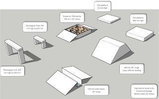
The original CAD model of the obstacle course, constructed
over several weeks by our indefatigable teaching assistants,
seniors Josh and Claire

The testing included nine phases (any of which could be skipped) all while carrying a payload. The teams would go through two gates of different sizes, over a gravel pit, up onto platforms of varying heights of 50 and 100 mm, push a block with the mass of one kilogram, go across a chasm, and make their way up a 45° incline. At the end of the run, the robot would be required to drop off the payload. The driver for each team would first do this routine while watching from nearby, and then once again using only a first-person camera view.

Davis gets his team's robot up onto the 50 mm platform with
no worries at all

The first robot to test was the "Trapezoidal Tank”. This robot was built by Nolan, Davis, and Alan. They felt ready for the first trial of the course, but decided to skip the 45° incline. Everything ran smoothly until the payload drop at the very end. They realized something was wrong.

The payload mechanism’s motor came unplugged!

Davis, the driver, thought up an idea. The payload was resting on top of the robot. What if he just flipped the whole robot over? Using the tank’s "tail", he flipped the robot up onto its end and delivered the payload.

Although not able to climb the full 45 degree slope, with a slight
modification the Trapezoidal Tank was make it at 40 degrees

A moment of pure glory! Davis upends the entire robot and performs
the obligatory victory dance!

On the camera-only run, the course was successfully completed again with only one obstacle skipped.

Caleb taking things in his stride, as the long-legged robot effortlessly
clambers over the gravel pit obstacle

Caleb attempts to steer by camera only--
no easy feat! 

Pushing the one-kilogram block away, the package waiting to be
delivered is clearly seen on the right-hand side of the robot

This complex (and squeaky) maneuver involves a series of
high-torque gymnastic activities


Next up was “Daddy Long Legs,” a robot with motorized wheels attached to extended legs. It was built by Caleb, Sydney, and Zach. Caleb, the driver, slowly completed the run, also skipping the very difficult 45° incline. On the camera-only trial, the robot was not able to place the payload in the designated area.

Anaconda brings its bulk to bear on a one-kilogram block of wood

This monster robot leaps 100 mm platforms with
a single bound!


Next was “Anaconda”, built by Sam P., Isaiah, and Pedro. It’s most notable feature? The robot’s tracks could rotate all the way around to point in the opposite direction. Sam P. took the wheel, and on his first run, he only skipped the smaller gate. On the camera-only run, he made it through the same obstacles without any issues.

James steers the Iron Horse through both gates and up onto
the 100 mm platform

Finally, the "Iron Horse” entered. This robot was built by Sam K., James, Joshua, and Kaitlyn. The design was simple yet effective. However, the extra mechanism they had added to their robot at the last minute broke! It was designed to help them get up onto the two platforms. Fortunately, there was enough power available for it to slowly assist with the obstacle it was built for.

Charging over the gravel pit with a huge ground clearance

Shortly after, that extra mechanism fell off and so did the payload. In a lengthy and complicated series of maneuvers, James used the one-kilogram block to push the payload over into the designated area.

End of the road: the Iron Horse capsizes while trying to free its
jammed package (the small yellow catch was supposed to release
and allow the hinged door to fall)

On the camera-only run, the Iron Horse's payload wouldn’t release. James used the gravel pit to try to get the payload to come loose, but the robot flipped over. He attempted to flip the robot back over, but it tipped over on its side instead. This run was incomplete.

The lesson to be learned for these four groups? Each problem can be solved in many different ways, but some are more effective than others. In every problem you encounter, consider those many solutions and then choose the most effective one.